A guest article by Thomas Chen, Pratool Gadtaula, and Dennis Chen
Last year, this blog had a post on building a musical synthesizer with an Arduino. This post breaks that down in more detail. We explain the theory behind parts of the system, how to write the software that goes with the hardware, and the challenges faced in creating a synthesizer that could play a large range of sounds and how we dealt with them in software.
Demo
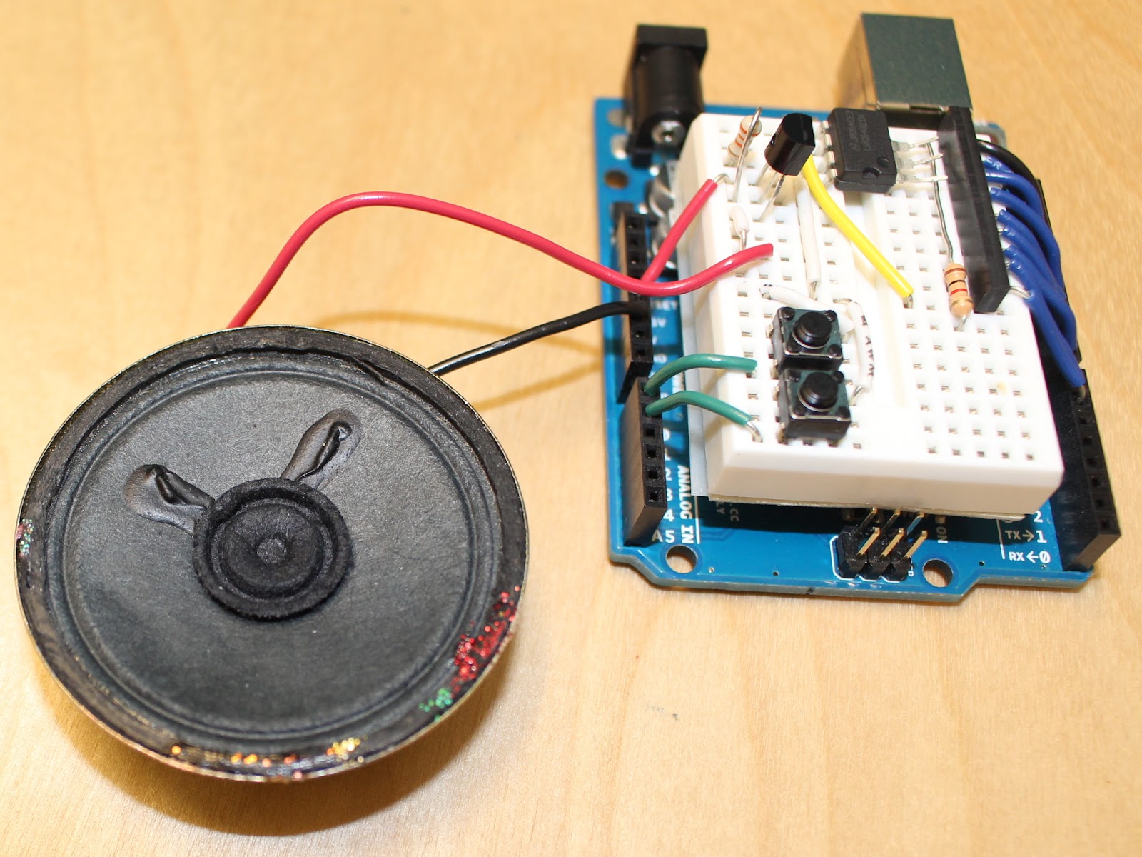
Here’s a short video of our synthesizer in action, if you want to see what your final product might look like.
Building an Arduino Synthesizer
A synthesizer is an instrument that generates electrical signals. By using these electrical signals to create waveforms, a synthesizer can make nearly any kind of sound. Sounds are mainly described by two factors: pitch and timbre. The pitch of a sound is how high or low it sounds. The timbre is the “character” of the sound - if two sounds of the same pitch seem different, they have different timbres. For this project, we show you how to create a synthesizer that can control both pitch and timbre to create different sounds. We provide hardware schematics and the code used in our synthesizer so you can easily follow our example for your own projects.
The Hardware
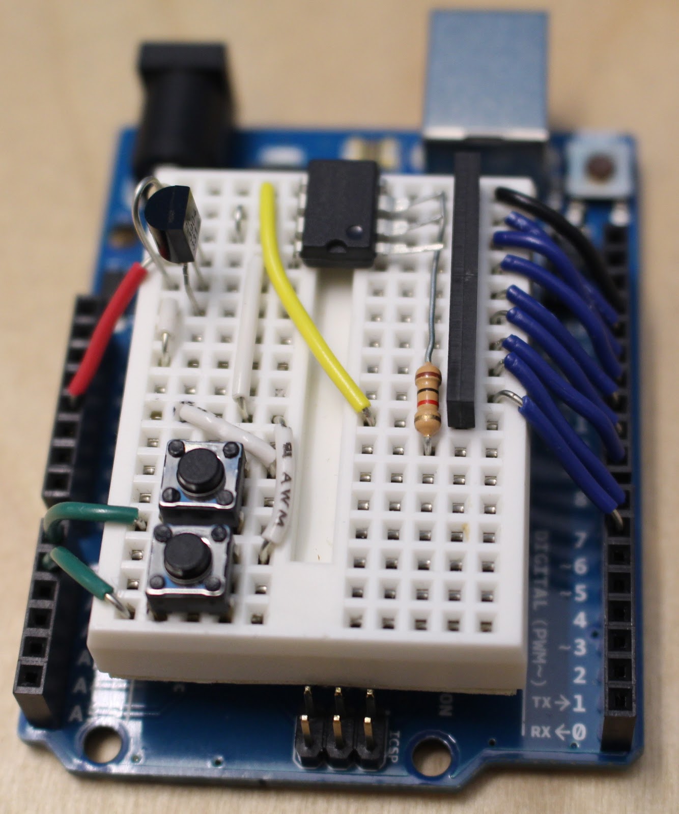
Here is a schematic of the circuit (we used the SoftSysSynth design). Below we describe the function of each component of the circuit.

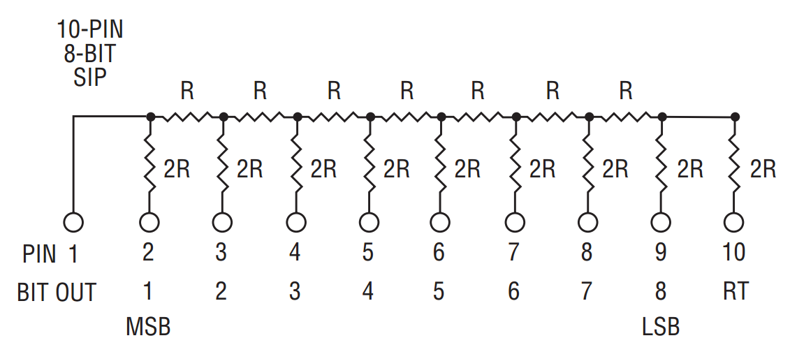
Resistor ladder (Digital to Analog Convertor)
The resistor ladder (part A in the circuit diagram) is used to write an analog voltage from a series of digital pins. For instance, the additive voltage coming out of one of the pins is 2.5 V. The next has 1.25 V, then 0.6125 V and so on, with each progressive digital pin outputting half of the previous pin’s voltage. This means that even though digital pins can only be on or off, we can set the output almost anywhere between 0 V and 5 V.
Buffer
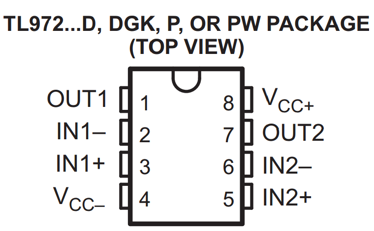
Next is a buffer (part B in the circuit diagram) with the TL972p operational amplifier. We are using only one of the two op amps in the integrated circuit (IC). By connecting OUT2 with IN2-, the voltage from IN2+ is preserved in OUT2 with only negligible current being drawn. Remember to connect VCC- to ground and VCC+ to the Arduino’s 5 V power.
Transistor
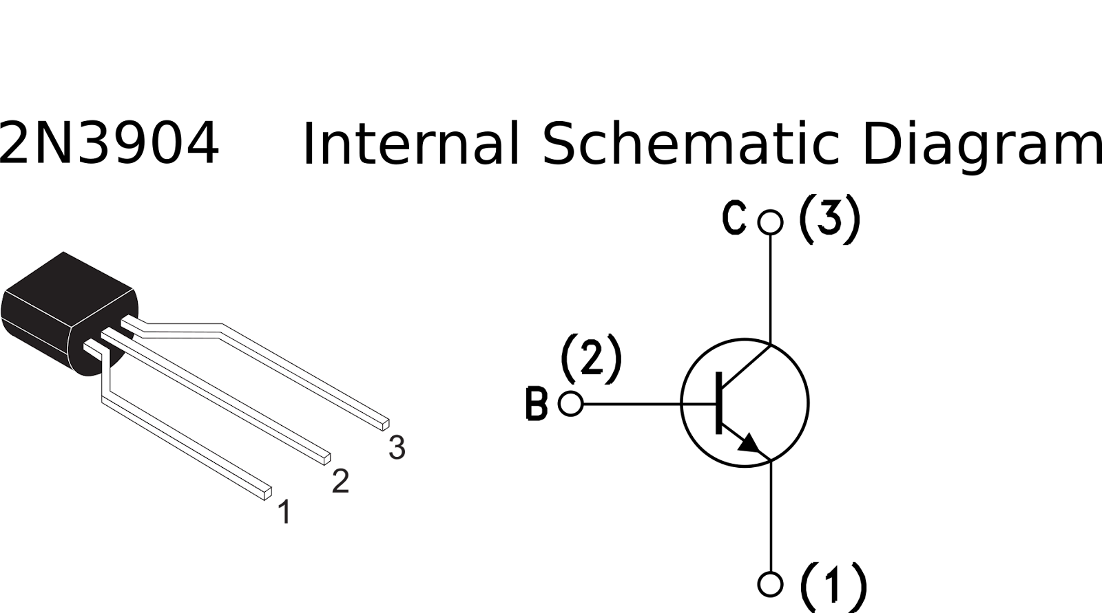
There is an NPN transistor (model 2N3904) after the filter for driving the speaker. That is, the transistor increases the current, thus amplifying the signal, making it strong enough so that the speaker picks it up. While the transistor is clearly not linear, it is good enough for human hearing at the frequencies we were able to generate. The resistor is put in before the transistor to avoid overamplification of the current. If the speaker you’re using needs more current, decrease this resistance.
The Code
Once you have the synthesizer hardware working, it’s time to get into writing software. If you’d like to just use our code and aren’t interested in the specifics, click here to see the code that you can copy/paste into your arduino IDE. For those of you who are figuring things out on your own, we’ll give you a brief overview of the questions we think you’ll end up asking yourself along the way when you program the synthesizer, and the strategies we used in writing our code to address them.
How do I get started?
The first thing to do is to get your Arduino writing values out to the digital to analog convertor. There are 8 pins on the DAC that you write into (the other two pins are the analog output of the DAC and ground), and you may notice that writing HIGH or LOW values to the 8 pins can be represented with a byte in arduino. For example, the byte 0B11110111 could represent “write a LOW value to pin 4 (counting from the right) and write a HIGH value to every other pin, where zeros represent LOW and ones represent HIGH.” Turns out that the way the DAC is set up, writing the byte values from 0 to 255 into the digital pins of the DAC maps to an analog output between 0 and 5 volts. So writing the byte B00000000 results in an analog output of 0 volts, and writing the byte B11111111 results in an analog output of 5 volts.
Below is what a first pass at writing a function that writes a byte into a DAC might look like.This function was written by Allen Downey. The original source for this is: https://github.com/AllenDowney/SoftwareSystems/blob/master/hw04/wave/wave.ino :
void writeByte(int x) {
int pin;
for (pin=13; pin>=6; pin--) {
digitalWrite(pin, x&1);
x >>= 1;
}
}
Once you can write a byte to the DAC, you have the power to get the DAC to output an analog value between 0 and 5V. But to get the speaker to make a sound, you’ll have to output a waveform from the DAC. Let’s try adding some code so the DAC will output a waveform over time. The code below generates a sine wave with amplitude 127 and an offset of 128 (preventing us from going into negative voltage).
byte counter = 0;
...
void loop(){
byte sinVal = byte((127 * sin(2*PI/256*counter)) + 128);
writeByte(sinVal);
counter++; //this will overflow and turn back to 0 after 255 because counter is a byte value
}
...
Now if you plug in the speaker you should be able to hear the sine wave that your synthesizer is generating! You may notice that it’s pretty low frequency.
I want my arduino to play a specific note, not any old sine wave. How do I do that?
To play a specific note, you’ll need your Arduino to write values to the DAC at a specific frequency, not just at whatever rate the loop() function runs at. To do that, Arduinos have built in timers that will take care of this kind of timing for you. They take a bit of setup to get working, but you should take a look at this fantastic tutorial that describes how to use timers: http://www.instructables.com/id/Arduino-Timer-Interrupts/?ALLSTEPS
We recommend that you use timer 1 on the Arduino (there are three timers on the arduino: 0, 1, and 2) for this task, since timer 1 allows for the greatest range of timer interrupt frequencies. The code looks daunting, but if you follow the tutorial, it’s mostly copy pasting code and tweaking some parameters. The main parts of the code needed to generate a sine wave at a specific frequency are below. Once you get it working, try changing the sine wave frequency by changing the waveFreq variable! What happens as you increase it and consequently increase the timer interrupt frequency?
byte counter = 0;
void setup(){
//set input output modes of pins that write to the DAC
DDRB = 0B11111111; //set pins 8 to 13 as outputs
DDRD = 0B11000000; //set pins 6 to 7 as outputs
//turn off interrupts
cli();
initializeTimerOneInterrupt();
long waveFreq = 10; //Edit me to try different wave frequencies!
setTimerOneInterrupt(waveFreqToCompareReg(waveFreq));
//enable interrupts
sei();
}
//timer one outputs waveforms
void initializeTimerOneInterrupt(){
TCCR1A = 0;// set entire TCCR1A register to 0
TCCR1B = 0;// same for TCCR1B
TCNT1 = 0;//initialize counter value to 0
//PRESCALER = x1
// turn on CTC mode
TCCR1B |= (1 << WGM12);
// Set CS10 bit for 1 prescaler
TCCR1B |= (1 << CS10);
// enable timer compare interrupt
TIMSK1 |= (1 << OCIE1A);
}
void setTimerOneInterrupt(short compareReg){
//Set compare register
OCR1A = compareReg; //(must be <65536)
}
short waveFreqToCompareReg(long waveFreq){
long WAVELENGTH = 256;
long interruptFreq = waveFreq * WAVELENGTH;
short compareReg = (16000000L) / (interruptFreq) - 1;
return compareReg;
}
//Timer one interrupt handler that writes out waves to DAC
ISR(TIMER1_COMPA_vect){
byte sinVal = byte((127 * sin(2*PI/256*counter)) + 128);
writeByte(sinVal);
counter++;
//this will overflow and turn back to 0 after 255
//because counter is a byte value
}
It still sounds terrible and when I increase the frequency beyond 30 Hz the sound doesn’t seem to get any higher pitched, what gives?
We’re running up against the limits of the Arduino’s computational power! It doesn’t matter if the timer is being triggered thousands of times per second if the code that runs when the timer interrupt handler is triggered is slow. The code in the ISR(TIMER1_COMPA_vect) function is taking too long to run so we can’t generate sine waves of high frequencies. Is that problematic? Well, low frequencies sound terrible on our dinky speakers, and the highest note on the piano is about 4.2 KHz, which we’d ideally like for our synthesizer to be able to reach if we want a synthesizer that can play a wide range of music. Unfortunately, right now we’re pretty far away from it. But there are a few tricks we can use to get there...
Using lookup tables for faster speeds
The first thing we can do is to precompute the values of the sine that we plan on writing to the DAC and to store those values into an array. It’s much faster to access an element in an array than it is to calculate the sine of a number on the Arduino! By precomputing the values that we plan on writing to the DAC, we can make the Arduino’s life much easier and speed it up. If we compute sine values and save them into an array in the Arduino setup function, performance gets drastically because performing mathematical operations like division and sine on the Arduino is costly.
We call a function in setup() called createSinLookup() that will precalculate sin values and put them in an array called sinWave that we can index into later.
byte sinWave[256];
setup(){
…
createSinLookup();
…
}
void createSinLookup(){
for (int i=0; i<256; i++) { // Step across wave tables
float v = (127*sin((2*PI/256)*i)); // Compute value
sinWave[i] = byte(v+128); // Store value in lookup table
}
}
…
ISR(TIMER1_COMPA_vect){
writeByte(sinWave[counter]);
counter++;
}
Run the code and you will see that we can increase the wave frequency more before we hit the speed limit! The wave is still relatively low frequency but we’re slowly getting there.
Improving on WriteByte
The writeByte function we have is pretty slow since it writes to pins one at a time. We can make the writeByte function an order of magnitude faster by writing directly to the registers that store the pinout values. It turns out that we don’t have to call the slow digitalWrite function for each bit value we want to set - we can set them all at once! It takes a bit of finagling though:
void setup(){
...
//set input output modes of pins that write to the DAC
DDRB = 0B11111111; //set pins 8 to 13 as outputs
DDRD = 0B11000000; //set pins 6 to 7 as outputs
...
}
void writeByte(byte val){
byte portDbyte = val << 6;
byte portBbyte = val >> 2;
PORTD = portDbyte;
PORTB = portBbyte;
}
What’s going on here? Well, we want to write digital values out to pins 6 to 13. The Arduino associates specific register values with the value that gets written out to an individual pin. Turns out that pins 6 and 7 are represented as the first 2 bits of a byte referred to as port D, and pins 8 through 13 are represented as the last 6 bits of a byte referred to as port B. We shift the byte we wish to write and directly set the portD and portB bytes in order to write out to pins 6 to 13.
There is a danger to writing directly to these ports- now you can’t trust any values that we read from ANY pins on port D or port B. So don’t try to use pins 3, 4, or 5 for digital read operations. We ran into problems trying to connect our buttons to those digital pins. Instead, you can plug things into the analog pins and perform digital read on those if you need more pins.
To speed things up even more, we decided to replace the shift left six and the shift right two operations with lookup tables. Can you figure out what additional code is needed to get the writeByte function below to work, where shiftLeftSix and shiftRightTwo are variable names for lookup tables? You’ll probably have to populate the tables in the Arduino setup. Take a look at the createSinLookup() function from above.
void writeByte(byte val){
byte portDbyte = shiftLeftSix[val];
byte portBbyte = shiftRightTwo[val];
PORTD = portDbyte;
PORTB = portBbyte;
}
Don’t run the code just yet, there’s still some work to do!
Reversing the bits
We’re writing the bits in backwards to the DAC because of the way things are wired up in our particular circuit. Did you notice that we were compensating for this in the original slow writeByte but didn’t do it in the new writeByte function? Now that we’re directly writing to the ports, we have to be careful and make sure that the bits are still reversed, otherwise we won’t be getting the output we expect! Reversing a byte before we write it every time seems like a pain. But we can make it easy and fast by reversing the bits when we first make the wave lookup table. If you’ve connected your resistor array in the opposite way as ours, this step is unnecessary.
void createSinLookup(){
for (int i=0; i<256; i++) { // Step across wave tables
float v = (127*sin((PI2/256)*i)); // Compute value
sinWave[i] = reverse(byte(v+128));
// store reversed value in lookup table
}
}
byte reverse(byte inb) {
//reverse function from
//http://stackoverflow.com/questions/2602823/
//in-c-c-whats-the-simplest-way-to-reverse-the-order-of-bits-in-a-byte
byte b = inb;
b = (b & 0xF0) >> 4 | (b & 0x0F) << 4;
b = (b & 0xCC) >> 2 | (b & 0x33) << 2;
b = (b & 0xAA) >> 1 | (b & 0x55) << 1;
return b;
}
Shortening the wave lookup table
You may have noticed that the lookup table for our sine wave holds 256 values. That doesn’t have to be the case. We could choose to represent one cycle of a sine wave as 128 values, 64 values, or even 8 values. That way, we can write more cycles of sine waves in the same amount of time, achieving higher frequencies. The tradeoff is that we lose resolution- our sine wave approximations will look less like actual sine waves and will sound worse. We found that having 32 values in our sine wave lookup struck a reasonable balance between wave resolution and higher output frequencies. One thing that you may notice is that all the numbers mentioned have been powers of two. Is it possible for the sine wave table to be 29 values long? Yep! But we chose powers of two for a specific reason, to be explained later.
Once you change the length of the wave table to be shorter than 256, you may have realized that the following code doesn’t work anymore, since you will be trying to access an index that is out of bounds once counter is greater than or equal to the length of your wave table.
byte counter;
ISR(TIMER1_COMPA_vect){
writeByte(sinWave[counter]);
counter++; //this will overflow and turn back to 0 after 255 because counter is a byte value
}
Well, you might say to yourself, I’ll just make counter a long value, and then take the counter modulo the length of my sinWave array to index into the array!
byte LOOKUP_TABLE_LEN = 29;
long counter;
ISR(TIMER1_COMPA_vect){
writeByte(sinWave[counter % LOOKUP_TABLE_LEN]);
counter++;
}
This works, but is unfortunately slow because modulo operations are slow on the Arduino. But one neat trick is that taking the modulus when the LOOKUP_TABLE_LEN is a power of two is fast if we use a shortcut: ANDing the counter value with the appropriate bitmask. For instance, to take a byte modulo 32, we can AND the byte with B00011111. To take a byte modulo 8, we can AND the byte with B00000111. Can you see why this works? We ended up using the following code to index into the wave array quickly:
byte LEN_32_INDEX_MASK = B00011111;
byte counter;
ISR(TIMER1_COMPA_vect){
writeByte(sinWave[counter & LEN_32_INDEX_MASK]);
counter++;
}
Don’t forget that you’ll have to change the other code that is dependent on the length of the lookup table, like the waveFreqToCompareReg() and createSinLookup() functions! Once you’ve gotten your code working, try cranking up the wave frequency. Your synthesizer should now be able to hit 4000 hz without a problem.
Playing a Song
After all this work, our synthesizer still can’t do much yet. It can generate very high frequency sine waves, but not much else. What if we want our synthesizer to play a song? It may sound difficult, but we’re actually pretty close. A song is simply a sequence of notes, and since we built our lovely synthesizer which can play many different notes (different frequencies), we change the frequency of the wave that the synthesizer is outputting over time in order to play a song.
To change the frequency of the wave we output, it’s time to bring in a second interrupt handler. The way it works is that a second interrupt handler reads from two arrays to determine when it 1) should change the frequency of the output wave and 2) what the new frequency should be. Below, we define the frequencies for a single octave and then the arrays to play that scale.
//define notes
const short C = 2093;
const short D = 2349;
const short E = 2637;
const short F = 2793;
const short G = 3135;
const short A = 3520;
const short B = 3951;
const short HIGHC = 4186;
//first note in notes and duration array is a sentinel value
//that is not actually played
//song will loop once it reaches the end of the array
short notes[] = {0,C,D,E,F,G,A,B,HIGHC};
int duration[] = {0,100,100,100,100,100,100,100,100}; // in .01s increments
int songLen = sizeof(notes)/sizeof(short);
int songIndex = 0;
int noteDuration = 0;
//timer two takes care of changing frequencies, checking at 100 Hz
void initializeTimerTwoInterrupt(){
TCCR2A = 0;// set entire TCCR1A register to 0
TCCR2B = 0;// same for TCCR1B
TCNT2 = 0;//initialize counter value to 0
//PRESCALER is x1024
//Set compare register
OCR2A = (16000000L) / (100*1024) - 1;//(must be <256)
// turn on CTC mode
TCCR2B |= (1 << WGM12);
// Set CS10 and CS12 bits for 1024 prescaler
TCCR2B |= (1 << CS12) | (1 << CS10);
// enable timer compare interrupt
TIMSK2 |= (1 << OCIE1A);
}
void setTimerOneInterrupt(short compareReg){
//Set compare register
OCR1A = compareReg;//(must be <65536)
}
short waveFreqToCompareReg(long waveFreq){
long interruptFreq = waveFreq * (long)LENGTH;
short compareReg = (16000000L) / (interruptFreq) - 1;
return compareReg;
}
//100 Hz timer two interrupt changes frequencies
ISR(TIMER2_COMPA_vect){
if(songIndex >= songLen){
songIndex = 0;
}
noteDuration++;
if(noteDuration > duration[songIndex]){
//go to the next note
noteDuration = 0;
songIndex++;
setTimerOneInterrupt(waveFreqToCompareReg(notes[songIndex]));
}
}
Now you’ll be able to play a scale on your synthesizer, and just about any song of your choice. Change the notes in the notes array for a more interesting tune!
Additional synthesizer features
Now that our synthesizer can play songs, you should feel free to pick up and explore what else you can get your synthesizer to do! Two options we chose to implement included adding a play/pause button, and having the timbre (type of waveform) of the wave change when a button is pressed. We describe these two features below. There are all kinds of other things you can look into, like having an envelope (attack and decay) generator, or figuring out how to play harmonics. The sky’s the limit!
Additional Synthesizer Features
Dealing with Buttons
Our circuit has two buttons which allow you to pause the music and change the timbre. These buttons run off a third hardware timer that periodically checks to see if buttons have been pressed. One thing to keep in mind when using buttons is that they are not mechanically “perfect.” During the button press, the electrical connection within the button will “bounce” before the button reaches its final position, meaning the button’s circuit will rapidly cycle between being connected and being disconnected. If you have something run as soon as the button circuit is closed, it could end up being triggered several times for every button press. You need to “debounce” the button so the software only reads it as completing once per press.
We used software debouncing in our project. This takes the form of checking the last time that the button was pressed. Every time the button circuit completes, we check the time and compare it to the last time the button was pressed. If the difference between the two is greater than a second, then we can be sure that the press was intentional, and we run our button-dependent code.
Pausing on Button Press
Now that we’ve solved the debouncing problem, we’ll explain how the buttons work. The first button is the pause button. This sets a “paused” flag in the software and saves the current frequency and waveform shape. It then “pauses” by playing a wave with zero amplitude, producing no sound. Once the button is pressed again, the “paused” flag is cleared and the synthesizer resumes playing from the saved note and waveform shape.
Changing Timbre on Button Press
The second button changes the timbre of the note by switching to a different waveform shape. Our implementation cycles through sine waves, sawtooth waves, and square waves in that order. Sine waves produce a pure, clear sound, while sawtooth and square waves have a harsher sound.
The final code we used for our synthesizer including the additional button press functionality can be found here:
We hope that this tutorial has been helpful and that you’re inspired to play around with synthesizers on your own. Have fun and good luck!