Wednesday, June 26, 2013

A BAD Synthesizer: part three

Ok, this project has a name now.  Arduino-Based Analog Digital Synthesizer, or A-BAD Synth.

Here's what it looked like last time:


I made one small change, replacing the 104 capacitor with a 394, so that's about 4x bigger, which drops the range of the synth by about two octaves.

I ran it overnight and collected tuning data, then generated tables that map from each MIDI note (0 to 127) to the appropriate pot levels.

And here's what it sounds like:


 So far, so good. The next step is to add a digitally-controlled lowpass filter.  Here's what that looks like:


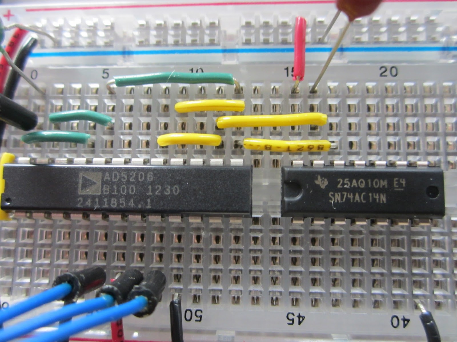
The filter is the three green wires and the capacitor you can't quite see in the upper left.  The longest green wire just brings the signal from the oscillator to the filter.  The short green wires hook up two of the digital pots in parallel.

The idea is that you can operate the filter two ways:

1) If you set the filter to a fixed cutoff frequency, it just applies a lowpass filter to all notes.

2) If you set the cutoff frequency to a multiple of the oscillator frequency, you can use it to shape the waveform.  And there are two ways you can tune the filter:

    a) If you set the filter pots and the oscillator pots to the same levels, you can use the capacitors to choose the multiplier.

    b) Or you can use the same capacitor for both and use the pot levels to set the multiplier.

I am experimenting with both, but at the moment it is not working as expected.  I am doing as much debugging as possible by ear, but at some point I might have to break out an oscilloscope.

At this point I have used the four pots across the top of the chip.  Next I am going to run the signal back across the bottom, using one pot for envelope generation and one for the VCA (voltage controlled amplifier).

Tuesday, June 25, 2013

Digital control analog synth: part two

As of last time, we had an RC oscillator using a digital pot as a variable resistor.  The digital pot provides 256 settings, so the synth can play 256 different frequencies, but none of these "notes" corresponds to a note in the tempered scale, which is what we would need to play conventional music.

So that got me thinking about the simplest way to generate tempered notes, and here's what I came up with.  If we wire up two digital pots in parallel, we get 256 * 256 = 65536 different frequencies, and it turns out that there is a useful range in the middle where the notes are only a few cents apart (a cent is 1/100 of a semitone, and a semitone is the difference in frequency between two adjacent keys on the piano).

So there should be a setting for the two pots that yields any desired frequency, within 2-3 cents, which is a tolerable accuracy of tuning for most listeners.

Here's the wiring of the digital pots from last time:


And here's what it looks like now with the second pot in parallel:


The only difference is the two wires the connect the two pots, and a new yellow jumper that connects the output of the oscillator back to the Arduino.  Why?  Because we are going to tune the oscillator by sweeping through the pot settings and measuring the output frequencies.

Here's what the Arduino code looks like:

https://github.com/AllenDowney/a-bad-synthesizer/blob/master/synthesizer/synthesizer.ino

And here's the Python code that reads data off the serial port and processes it:

https://github.com/AllenDowney/a-bad-synthesizer/blob/master/python/tuner.py

During the measurement phase, the tuner reads data off the Arduino and writes it to a Redis database.  During the processing phase, it reads the database and makes a lookup table that maps from MIDI note to the digital pot settings.  It generates tables that looks like this:

https://github.com/AllenDowney/a-bad-synthesizer/blob/master/libraries/scale/table.h

I put the table into a library so any Arduino sketch that wants to play MIDI notes can import it.  I'll show an example (and an audio file) next time.

Thursday, June 20, 2013

Digital control analog synth: part one

Last time I presented my spiffy way of connecting a 3.5 mm audio jack to a breadboard.  This time I am going to do something with it: the first step toward a digitally controlled analog synthesizer.

I got the idea from this post by Gian Pablo.  As he explains:
In a nutshell, I am using a 74C14 Schmitt Trigger hex inverter to build a number of standard resistor/capacitor oscillators. For each of these, the variable resistance value (ie variable voltage) is provided by one of the digital pots on the AD5206.
He explains some of the nice properties of this design:

1) It's made from a small number of cheap parts.

2) Using an analog synthesizer to generate audio leaves the Arduino free to run the control code.

3) Because the digital pot uses SPI, you only need three digital pins to control six pots.

Here's what the whole setup looks like:


The Arduino provides power to the breadboard.  I am using 3.3V because when I use 5V, bad things happen, and I don't know why.

Here's a closer look at the wiring:


The AD5206 is the digital pot.  It costs $4.89 at Digikey, but the nice people at Analog Devices sent me a few free ones as part of their University Program.  Thank you, AD.

The 74AC14N is a hex Schmitt-trigger inverter, which you can wire up as six oscillators.  This is one of the building blocks Nicolas Collins uses in his amazing book, Handmade Electronic Music (affiliate link).

Here's a close-up of the osciallator:


The capacitor is a 104 (0.1 uF).  Paired with the 100 kOhm digital pot, it yields tones in a musical part of the audio range.  But we'll do more tuning later.

Here's a close-up of the pot:


I am using one of the pots as a variable resistor.  The red and black wires are power.  The blue lines from the Arduino are the SPI interface.  To control the pot, I started with the code in this excellent tutorial.

Finally, just for completeness, here's the connection to the audio jack:


The yellow wire goes to pin 1; the black wire is ground.

And here's what it sounds like:


Friday, June 14, 2013

Think DSP

I am thinking about a new project.  Think Bayes is almost finished, and I have a few ideas for the next book.  One possibility is a computational approach to Linear Algebra.  But the idea I am most excited about for now is Digital Signal Processing (DSP).

I imagine two threads: one is a software-based approach using Python with NumPy and SciPy.  The other is a hardware approach using C/C++ on Arduino.  Since I am more comfortable with the software, I am tackling the hardest part first.  And I am starting with an Arduino-controlled analog synthesizer.

I'll present the design later.  But before I get to the actual synthesizer, I want to start with something I "invented" that might be useful: a cheap and easy way to connect a 3.5 mm audio jack to a solderless breadboard.

There's a $5 solution here: http://store.curiousinventor.com/plug-in-bread-board-stereo-1-8-quot-audio-jack.html

Or you can get the jack for $1.50: https://www.sparkfun.com/products/8032

And a PCB breakout board for $0.95: https://www.sparkfun.com/products/10588

And solder them together.  But if you already have the jack and some break away-female headers, you can make your own solution.  Here's how:

1) Make sure the holes at the top of the female headers are big enough for the pins on the jack.  It looks like they come in at least two sizes:


The ones on the left are too small.  The ones on the right are good.

2) Break off two headers with 5 pins each (or you can make one of them smaller).  UPDATE: after more experimenting, I recommend headers with longer pins than the ones below (stackable headers).  The short pins do not make a good electrical contact with the breadboard, and they do not make a solid mechanical connection.


A few suggestions for breaking so-called break-away headers:  (a) you can't break between two adjacent holes; you have to sacrifice a hole in between; (b) before cutting, use pliers to remove the metal pin from the hole you are sacrificing; (c) you can use wire cutters to make the cut, but you should wear eye protection -- the pieces go flying!  (d) you can use wire cutters and sandpaper to clean up the cut edge.

3) Put the headers into a breadboard and then stack the jack on top.  Four pins go into the back header; one pin goes into the front (so the front really only needs to have 1-2 pins).  Use super glue to hold the whole thing together.


Here's the other side (with the rough edges I didn't bother to sand).


So there it is.  Just a little bit cheaper than using a PCB breakout board, and no soldering.