Ok, this project has a name now. Arduino-Based Analog Digital Synthesizer, or A-BAD Synth.
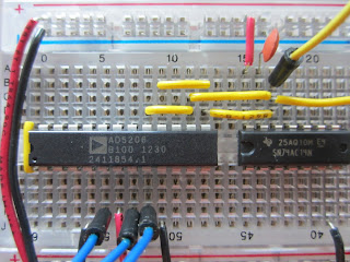
Here's what it looked like last time:
I made one small change, replacing the 104 capacitor with a 394, so that's about 4x bigger, which drops the range of the synth by about two octaves.
I ran it overnight and collected tuning data, then generated tables that map from each MIDI note (0 to 127) to the appropriate pot levels.
And here's what it sounds like:
So far, so good. The next step is to add a digitally-controlled lowpass filter. Here's what that looks like:
The filter is the three green wires and the capacitor you can't quite see in the upper left. The longest green wire just brings the signal from the oscillator to the filter. The short green wires hook up two of the digital pots in parallel.
The idea is that you can operate the filter two ways:
1) If you set the filter to a fixed cutoff frequency, it just applies a lowpass filter to all notes.
2) If you set the cutoff frequency to a multiple of the oscillator frequency, you can use it to shape the waveform. And there are two ways you can tune the filter:
a) If you set the filter pots and the oscillator pots to the same levels, you can use the capacitors to choose the multiplier.
b) Or you can use the same capacitor for both and use the pot levels to set the multiplier.
I am experimenting with both, but at the moment it is not working as expected. I am doing as much debugging as possible by ear, but at some point I might have to break out an oscilloscope.
At this point I have used the four pots across the top of the chip. Next I am going to run the signal back across the bottom, using one pot for envelope generation and one for the VCA (voltage controlled amplifier).


No comments:
Post a Comment
Note: Only a member of this blog may post a comment.