I got the idea from this post by Gian Pablo. As he explains:
In a nutshell, I am using a 74C14 Schmitt Trigger hex inverter to build a number of standard resistor/capacitor oscillators. For each of these, the variable resistance value (ie variable voltage) is provided by one of the digital pots on the AD5206.He explains some of the nice properties of this design:
1) It's made from a small number of cheap parts.
2) Using an analog synthesizer to generate audio leaves the Arduino free to run the control code.
3) Because the digital pot uses SPI, you only need three digital pins to control six pots.
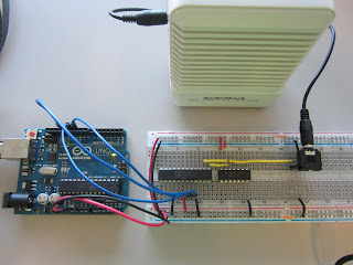
Here's what the whole setup looks like:
The Arduino provides power to the breadboard. I am using 3.3V because when I use 5V, bad things happen, and I don't know why.
Here's a closer look at the wiring:
The AD5206 is the digital pot. It costs $4.89 at Digikey, but the nice people at Analog Devices sent me a few free ones as part of their University Program. Thank you, AD.
The 74AC14N is a hex Schmitt-trigger inverter, which you can wire up as six oscillators. This is one of the building blocks Nicolas Collins uses in his amazing book, Handmade Electronic Music (affiliate link).
Here's a close-up of the osciallator:
The capacitor is a 104 (0.1 uF). Paired with the 100 kOhm digital pot, it yields tones in a musical part of the audio range. But we'll do more tuning later.
Here's a close-up of the pot:
I am using one of the pots as a variable resistor. The red and black wires are power. The blue lines from the Arduino are the SPI interface. To control the pot, I started with the code in this excellent tutorial.
Finally, just for completeness, here's the connection to the audio jack:
The yellow wire goes to pin 1; the black wire is ground.
And here's what it sounds like:


No comments:
Post a Comment
Note: Only a member of this blog may post a comment.